Very nice
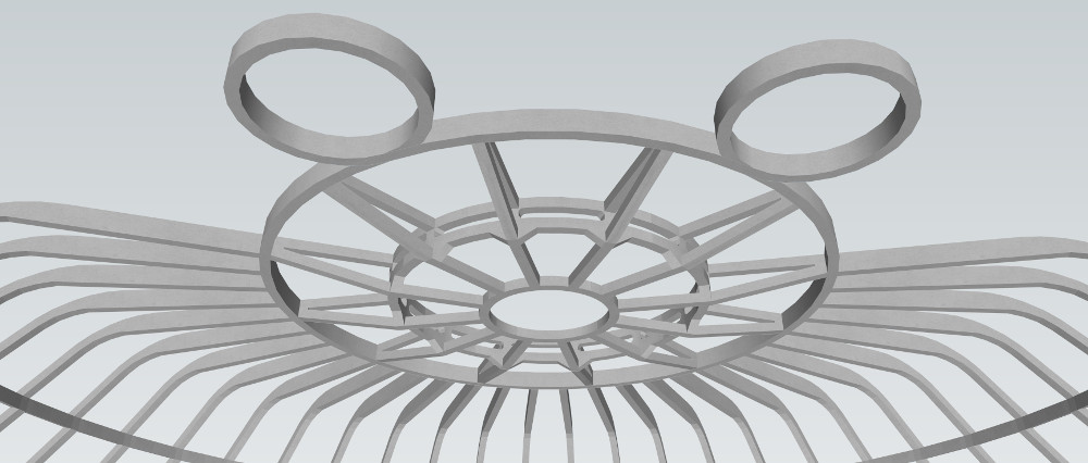

Oh NO!!! Don't tell me Disney has acquired the Trek franchise, too...

Just saw this thread Dan and you are making excellent progress!
I know you're going off of existing blueprints, etc, but if I may be so bold, you could drop the bridge down into the floor below to get the extra diameter you need to fit everything.")
") I wish I could give you advice on using Sketchup but I'm not very good at that program. Definitely follow the advice others have given for best utilizing your memory so you can keep working on it. I'm looking forward to see where you go with it!
I wish I could give you advice on using Sketchup but I'm not very good at that program. Definitely follow the advice others have given for best utilizing your memory so you can keep working on it. I'm looking forward to see where you go with it!
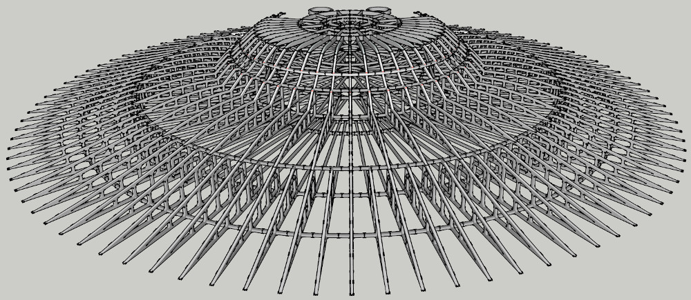
How big do you plan to print that?
How big do you plan to print that?
I've been wondering that myself... I need to fight the urge to make it as big as physically possible, which then comes with the additional challenge of where to put it when it's finished :P
Realistically I think it will about 4-5ft long, which is big enough for a decent amount of detail without being so huge that it falls apart or takes up my entire lounge.
Just need to make sure that the girders and things are strong enough to support the structure on the print, so it can't be too dainty.
Do you have any idea how much that would cost? I once designed something that was just a flat frame about 12x12 and it ended up pricing out at 400 on shapeways.
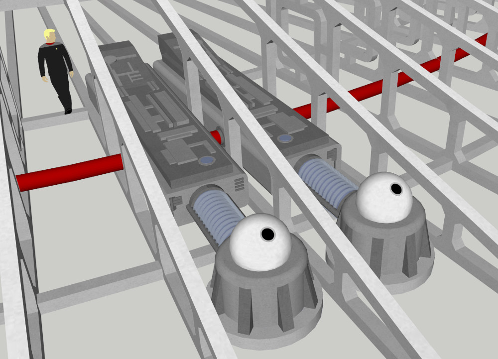

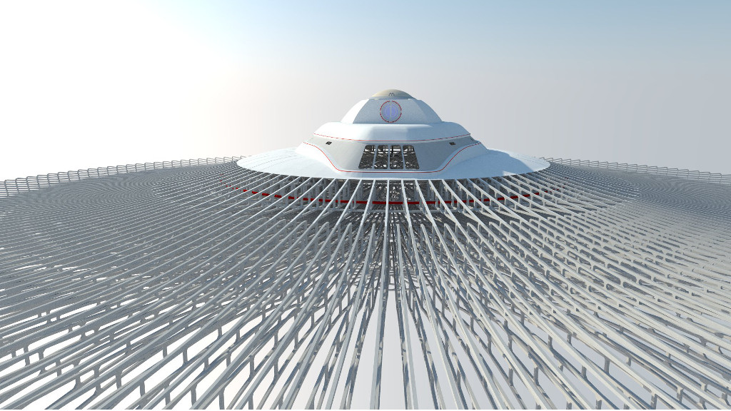
I've been trying to visualise what the phaser control hardware looks like beneath the turrets on the outer hull. Here's what I've come up with so far:
The red conduit is for the power, which I'll connect up to the intermix somewhere. I'll also have another conduit running to the computer core for the targeting/sensors etc.
While the red conduit looks cool, I doubt that they would route power that way. Most likely, they would have individual runs going up through the structure, into each of the phaser banks.
Hi Dan,
My thinking extrapolated from the series and the movies for the phasers were that:
1. The phaser energy is stored in 4 phaser energy banks
2. Each bank belonged to a phaser control room which was manned and could independently act.
3. Each phaser bank could pump their energy to any phaser emitter available to fire on a target.
4. All the phaser emitters and banks were connected to each other.
5. In the TOS series, the four phaser banks could be charged up from any source and all four could take the entire ship's output (actually more, since they burned out the warp drive).
6. In TMP, they put something in between the energy banks and the warp drive to boost power but failure of warp drive meant loss of phaser power.
7. In TWOK, they altered that so they could bypass the warp drive in case it wasn't available and fire them from auxiliary or battery power.
8. Phaser coolant
You could take a look at the episode "Balance of Terror" and the phaser control room shown there to perhaps give you a starting place for what the room might have looked like before the redesign in TMP.
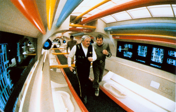
I'm going to colour code the conduits depending on their function, somewhat like this: (although no idea where this is supposed to fit on the ship...)

We use essential cookies to make this site work, and optional cookies to enhance your experience.