• Welcome! The TrekBBS is the number one place to chat about Star Trek with like-minded fans.
    If you are not already a member then please register an account and join in the discussion!

Refit/1701-A - 3D Model, Full Interior

DanGovier

Commander
Red Shirt
For something like 20 years now I've had this burning need to construct the Refit Enterprise as completely as possible in 3D. After a few failed / unfinished and frustrating attempts in Minecraft over the past few years, I'm ready to try again using proper 3D modelling software so that I can achieve the level of detail my inner geek craves.

I have to say I have been truly inspired by a number of people on this forum (blssdwlf, havoc92, CTM), you guys have set the bar so high that it'll be a struggle to make something that doesn't look like a child's toy in comparison ;)

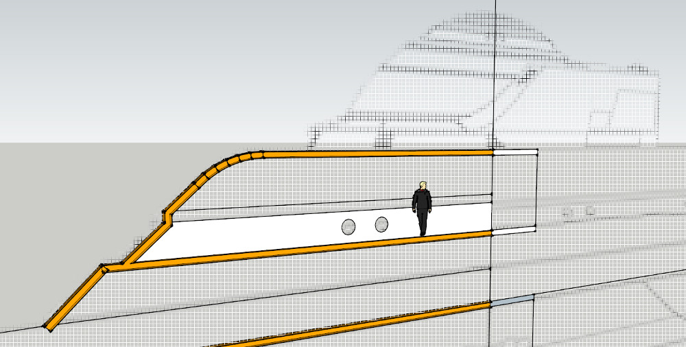
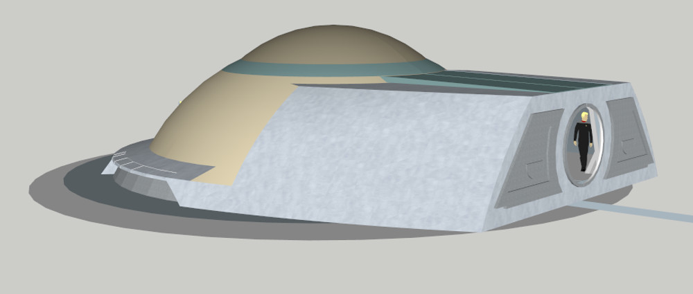
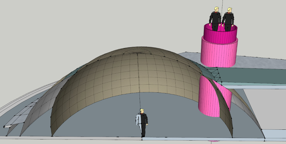
First of all I'm trying to get the scale right, so I'm going with a 305 metre design with 10 decks in the saucer. Each deck is 2.43m high with a floor thickness of 20cm. This seems to fit fairly well with existing blueprints without needing to fudge anything too much:

step02.jpg


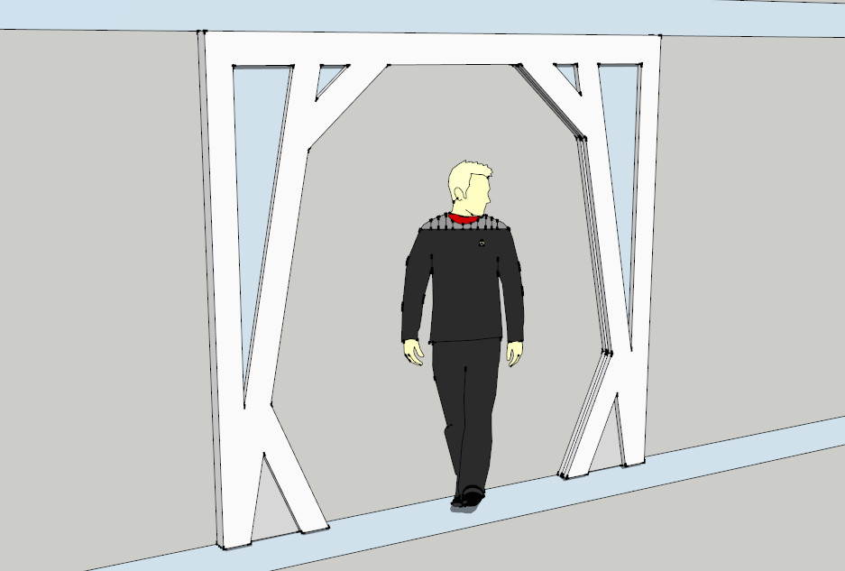
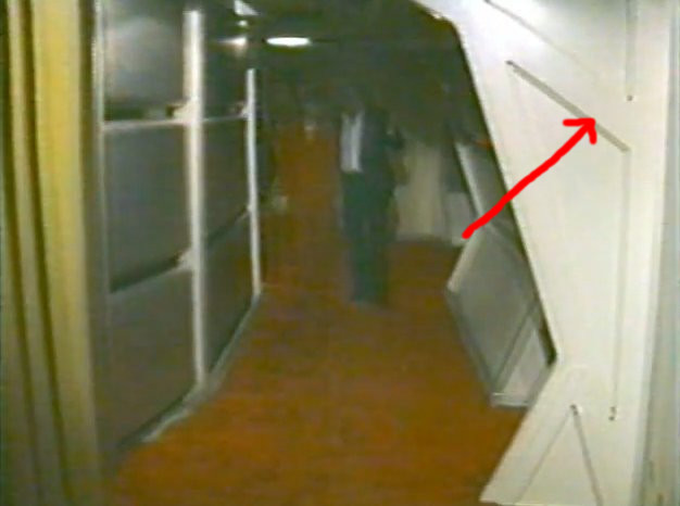
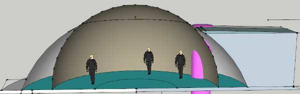
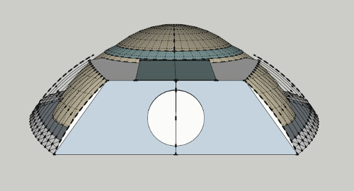
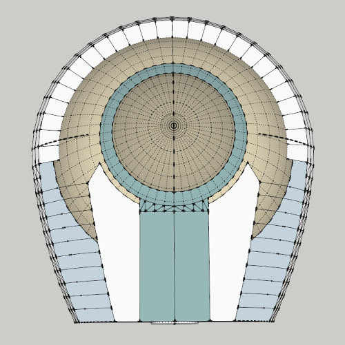
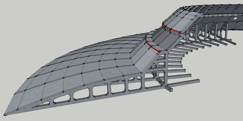
I want to build this as though it were real, so I'm going full on girders and i-beams throughout to support the internal structure. My ultimate goal is for all these parts to be 3D printable, so the structure needs to be strong:

step03.jpg


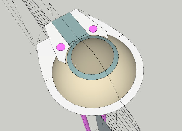
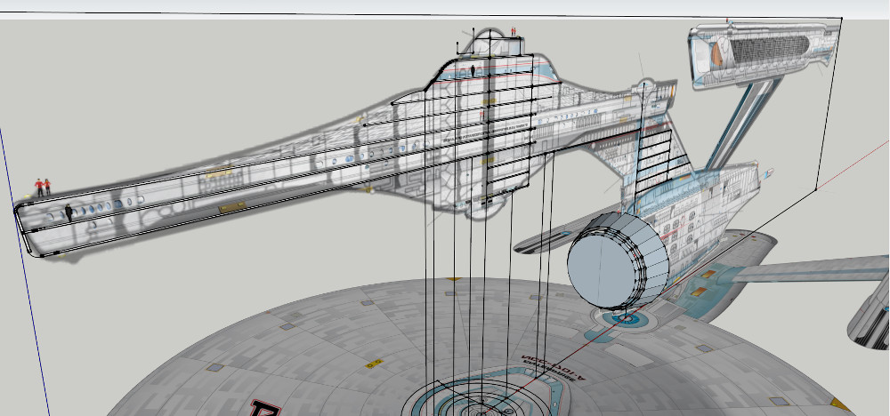
It's all very WIP at the moment, but hopefully you get the idea! :)

I'm sure it's going to be hilarious trying to stop the 3D printed nacelles from falling off...
 
Last edited:
This is a neat idea.

Just a thought, but for the primary hull pieces you might want to consider a standardized round hub on each deck with 16 (or 32) interlocking attachment points, that way you can build in a support system and have it terminate at a central location.
 
It looks like you're using Sketchup? It may choke with a project of this scale if you try to keep it to one file. Your best bet would be to break it up into smaller projects, maybe save it deck by deck.
 
I'm using Sketchup yep, for no other reason than it's free and I was impatient to get started ;)

I've re-done my layout slightly using Big Jim Slade's blueprints as a guide, and everything seems to be fitting a lot more cleanly now. I just can't seem to get Deck 2's little round windows in a sensible place... they look like they should be at head hight but the model simply doesn't fit that way.

step04.jpg


Have any of you guys seen a decent solution to this?
 
Either the decks aren't spaced the way one might assume or those aren't actually portholes despite their appearance.

A TMP refit done in SketchUp? Possible if one uses layers and groups. At some point I'm going to mike a Pike era Enterprise in SketchUp. I've already done a TOS era destroyer as well as a Class F shuttlecraft and a TAS freighter. I also want to do a TMP as well as TFF shuttlecraft.

So a TMP refit should be doable.
 
Oh, models have been done. Plenty of them on 3d warehouse. The issue is that DanGovier plans to do every deck and infrastructure. That level of detail can quickly lead to a huge file that Sketchup can't handle.
 
Oh, models have been done. Plenty of them on 3d warehouse. The issue is that DanGovier plans to do every deck and infrastructure. That level of detail can quickly lead to a huge file that Sketchup can't handle.


Yep, that's gonna be huge, if he creates global groups and creates them seperately then bring them in for the final result it should be better, But he's gonna need a good computer, GPU and CPU, I have the latest AMD FX Eight core chip and a pretty good mid range GPU also 16gb RAM and a file that big would choke my system too
 
I'll have to take a look at porting to 3DS Max or similar before it gets too complex. I have a quad core i5, 8GB RAM, and a Gainward GeForce GTX 460 GLH. Bit dated now, I've not been keeping up with the trend :P

It would actually be nice to get this into Unreal Engine 4 at some point too once I start on the fine details.
 
Just been playing around with the outer hull... loving those lines!

step05.jpg


The rim of my saucer is going to end up a little skinnier than the blueprints, but only by about 30-40cm. If I make it any deeper it will interfere with the other decks.
 
There's no reason deck 2 can't have larger ceiling height. Could be staggered too.

Not like the outside rim decks match the windows either if we go by the convention of there being 2 decks around the rim.

Lots of fun solutions. Make the ship larger (eeek). Be creative with decks- say around the rim actually being one deck around the rim, and then spit into 2 decks.

Then you get to the secondary hull and can have lots of fun.
 
Yep, I'll have a play with it and see which feels the most comfortable. Really don't want to make the ship bigger... I'm seeing it as a personal challenge to fit it all in using the canon dimensions. (dorsal... ugh)

There's also the fact actually that a lot of plans (and the polar lights model) have steps leading down into the officer's lounge.
 
First iteration of a corridor piece:

update_06.jpg


Does anyone have the measurements for the 'other' type of corridor? The type where one side is flat? These are wider on the angled side and structurally different:

update_06_example.jpg
 
I've been working on the bridge dome a bit tonight... man that's an awkward shape to model. Getting there though, and it's helping me learn Sketchup :P

update_07.jpg


The internal scale doesn't look too bad. The purple tube aligns with what I've always assumed to be the cap of the turboshafts on the top of the bridge module. Not sure if they'll need moving back a bit yet.

update_08.jpg


Anyone know what the acceptable width is for the turbolift? I've been looking at loads of plans but none of them have measurements on :(
 
A bit more progress on the bridge module. Once I make sense of the inner dimensions I'll start adding the actual girders and such to support the structure. I'm liking the double layered dome, it lends itself to being a very strong part of the ship. You'd expect that with it being the command centre.

update_09_b.jpg

update_09_a.jpg
 
Just been playing around with the outer hull... loving those lines!

step05.jpg


The rim of my saucer is going to end up a little skinnier than the blueprints, but only by about 30-40cm. If I make it any deeper it will interfere with the other decks.

I'm thinking, too, that if you drop the character silhouette down to what looks like would be the level below it, it's head will actually match with the height of the window ports. Then, the ceiling space above him could be what contains circuitry, conduits, computer processing nodes, etc.
 
I'm wondering if I can extend the officer's lounge around the outside edge of the teardrop and have deck 2 in the middle there somewhere. That way the portholes become ceiling windows, which makes sense because they are angled quite flat. Still working on the bridge module at the moment, it's proper fiddly.
 
Thanks Bernard, they're great and will certainly help with the internal arrangement. Looks like there is going to be plenty of room for the toilet and airlock area behind the bridge:

update_10_airlock.jpg

update_10.jpg


The turbolift is going to be a bit of a struggle though. if I make the lift car 6ft (180cm) wide and the shaft itself 2m wide it intrudes into the bridge area quite a bit. This is assuming of course that I line it up with the lumps on the bridge module. There is room internally to move the shafts backwards if required, I just like the idea of those lumps being the top of the turbolift hardware. I would also say that a 6ft turbolift should be the absolute smallest it could be because it's very cosy:

update_10_turboshaft.jpg
 
According to Shane Johnson, the outside of the turbolift should be about 10ft. Interior, slightly smaller, of course. But I would use 10ft. for the shaft diameter.

The inner diameter of the bridge itself is 36ft., to give you another dimension to work with, and if you can find a copy of "Star Trek Phase II: The Lost Series", it gives you the profile of the bridge's arched outer wall. The print I'm talking about is online somewhere. I'm not sure where. Sorry I can't give you a link.

The lower level of the bridge is 2ft. below the outer ring with 8in. steps for the Captain's Chair and Helm platforms.

I'd love to give you metric measurements, but the sets were built in the '70s in the US, so...

I'm watching this thread with great interest!

From what I've seen coming out of Sketchup from some people, there's no reason to use a pirated copy of Max in the future. Just sayin'. Learn Sketchup inside-out, and the principles will translate to other programs if you ever want to go pro.
 
If you are not already a member then please register an account and join in the discussion!

Sign up / Register


Back
Top