How to make a B/C deck superstructure
Another poster here, "Circusdog," has decided to start working on his own version of the classic 1701, and like me, he's using a CAD package (as opposed to a surface-modeler like Maya or Lightwave or the like).
He was having some trouble figuring out the best way to make the unusual shape of the B/C deck superstructure, and I've offered to post my step-by-step here to help him figure it out.
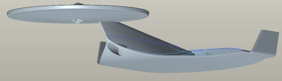
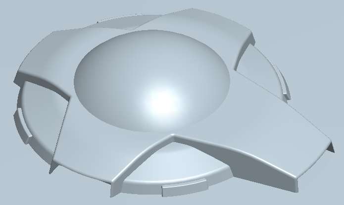
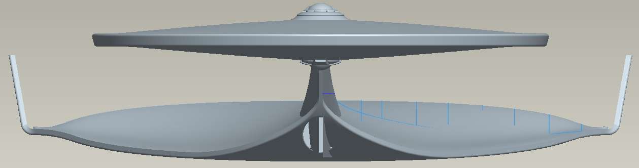
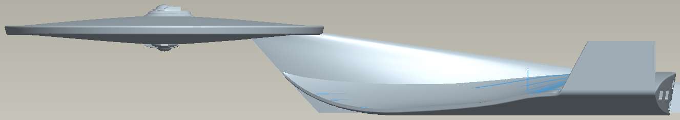
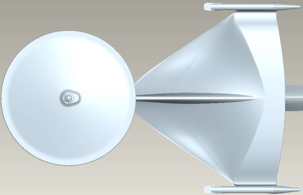
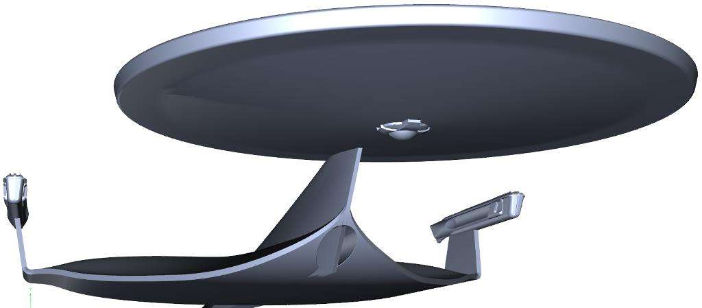
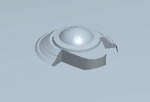
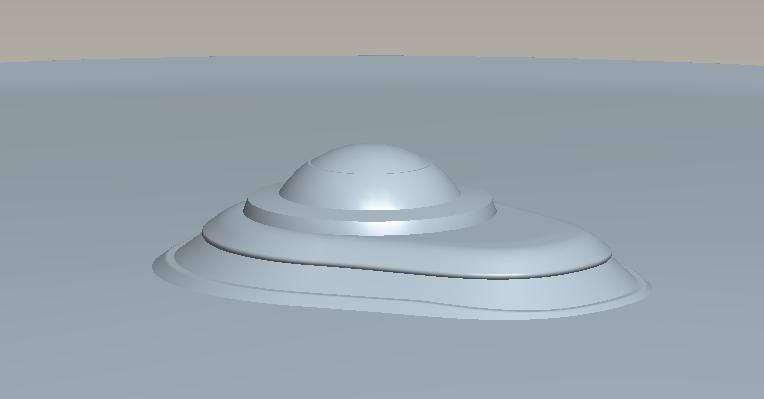
First... here's the topside of the Ariel's primary hull. I originally created it solely as a set of revolved shapes, and wasn't really planning to do this detail yet (since my focus remains on the secondary hull's complex topside). But I'll have to do it sooner or later, so I've gone ahead and done it now.")
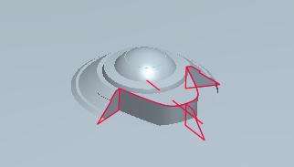
The first thing to do is to turn the revolved section into a smaller region, as seen below. It's important to make sure that you have the angle of the absent area as a changeable parameter, so you can simply adjust the angle of that cut-out area (and the tangent angle of the new section) on-the-fly as you tweak the shape.
Now, with the TOS Enterprise, the cylindrical "core" is perfectly adequate, but for TMP-era ships, you can't just sweep around a cylinder and get the shape right, so I added an additional volume to provide the "core" around which I'll be sweeping my shape. This should have a surface which is normal to the shape you want to achieve. I usually use conics to create this sort of shape... this path is defined by two symmetrical conic section, normal to the cut faces.
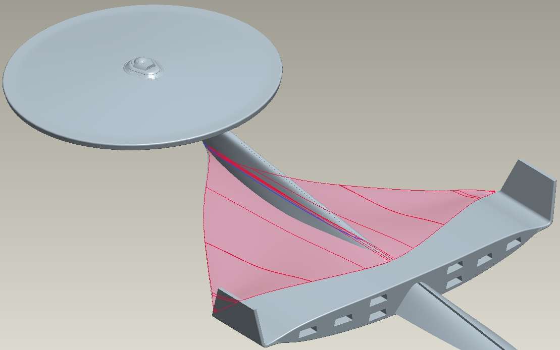
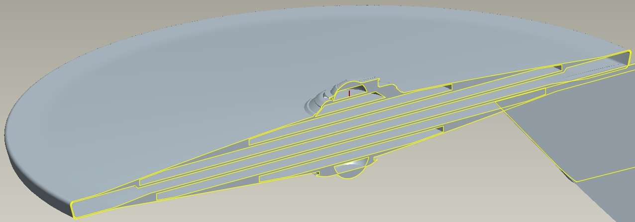
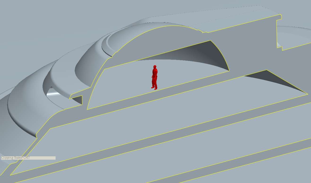
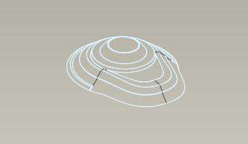
Now, you need to create the structure you'll be sweeping... a path, and at at least three sketches for cross-sections, as seen below. If you're not happy with the shape you're able to create using three sections, you can always add more (ensuring that they're symmetrical, obviously!). Each section needs to have the same number of drawing entities, and should have its origin at the same point, facing the same direction. I set my section origins in the innermost corner, facing upwards. If you don't get the origin right, the shapes will "twist" as the shape extrudes along the path, and you'll get a MESS.
(Note that you want the new, swept surfaces to be tangent to the existing surfaces. You need to have a surface adjacent to each of those sketch curve edges, so you can establish the tangency of the swept shape against those surfaces.)
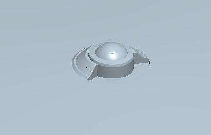
I'll show the result of that sweep in no-hidden-line wireframe mode. Now, in this case, I wanted my upper "lip" and lower "lip" for the inset region to be unrelated, so I left the lower lip out of the first sweep. (This is not necessary for the TOS ship, obviously!)
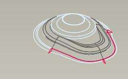
I created a sweep profile for the lower lip... this is a 2D sketch I created, projected onto the surfaces of the inset region. I created three profiles, again, just as before.
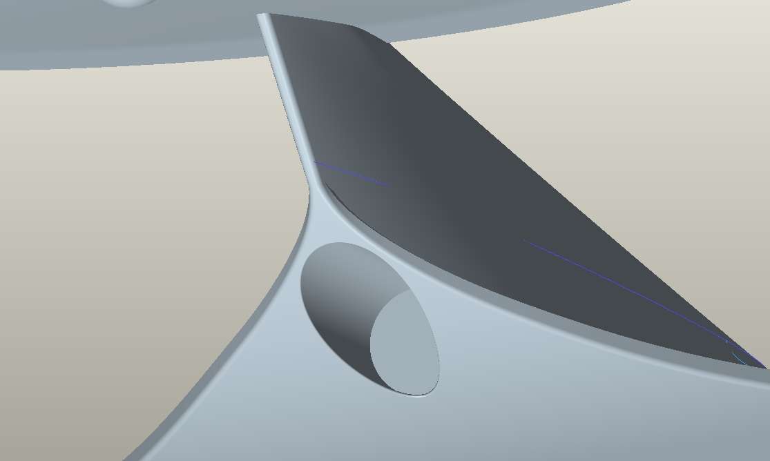
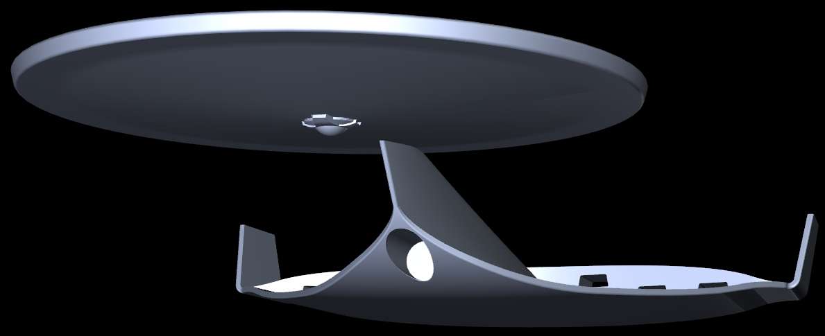
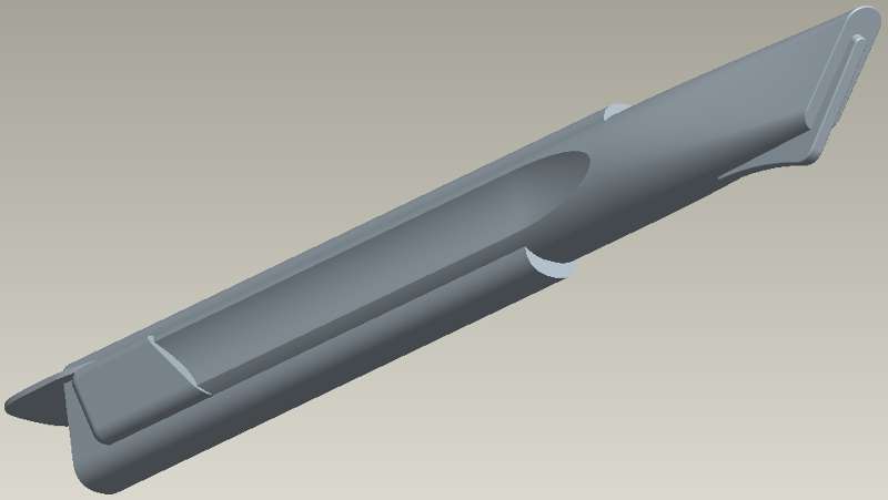
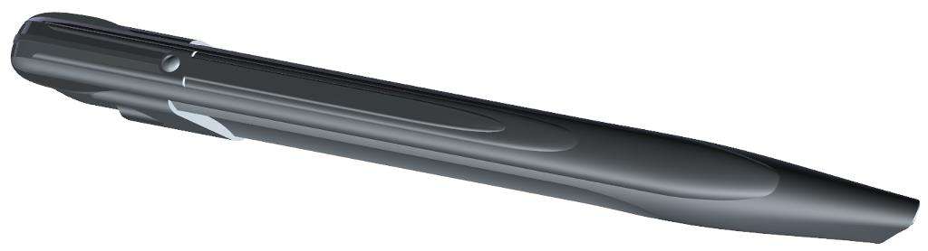
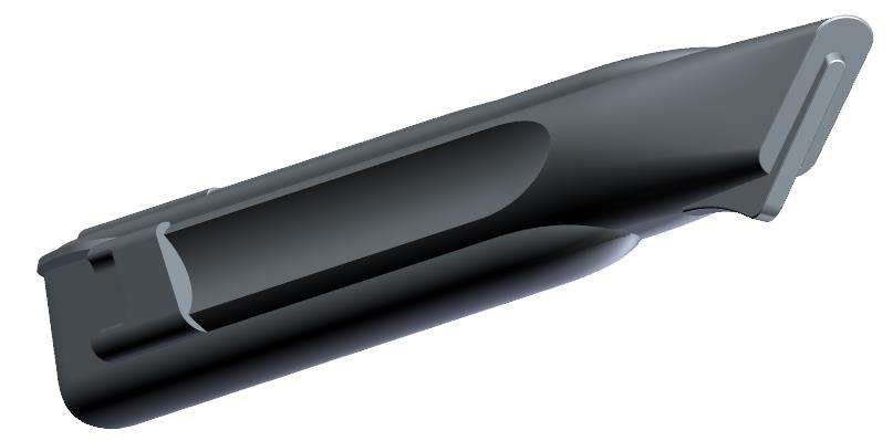
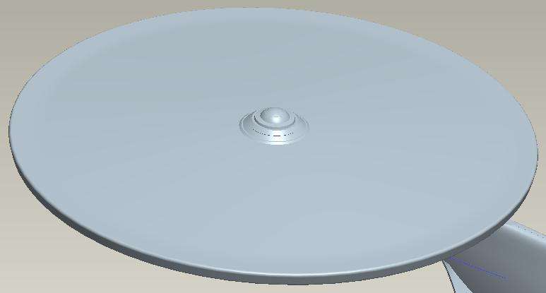
Here's the result. Note that I've added a few rounds to help make it look more like a real object... the rounds were not part of the original sweeps.
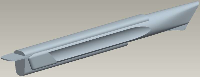
At this point, you start comparing your shape to the sketches (which you should have been doing all along, obviously, but now you make it into the "final" shape). You tweak the various parameters in your shapes... the "cut-out angle" for example... and adjust things to get as close as you can to the drawn images.
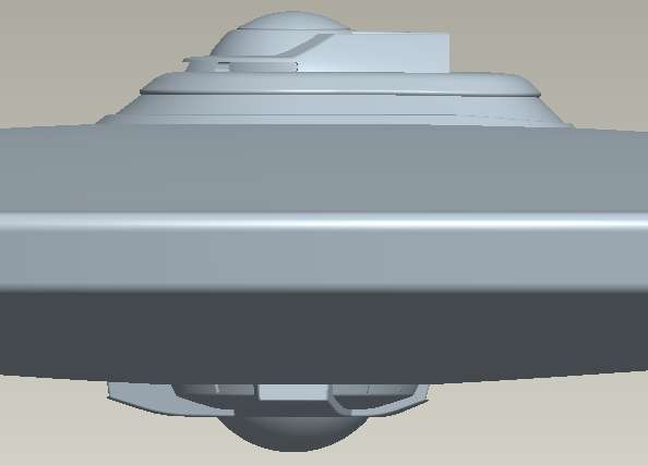
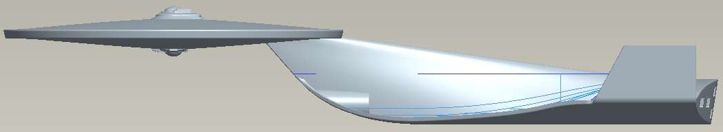
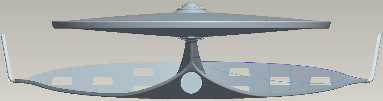
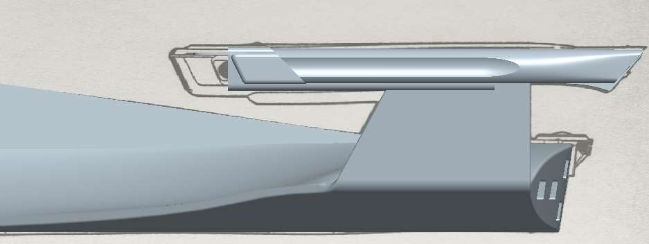
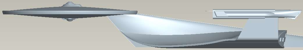
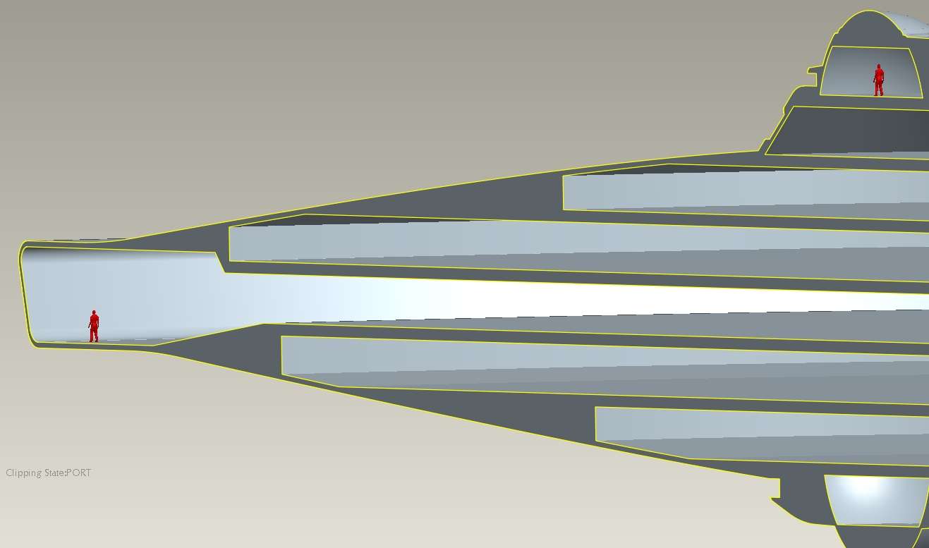
The following two images allow you to compare my final result to the "trace sketch reference" I'm using. The lateral view is nearly perfect... and I'm not inclined to make any further tweaks here.
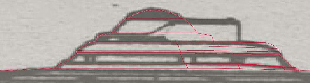
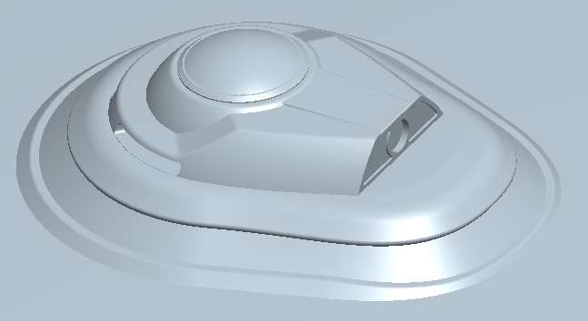
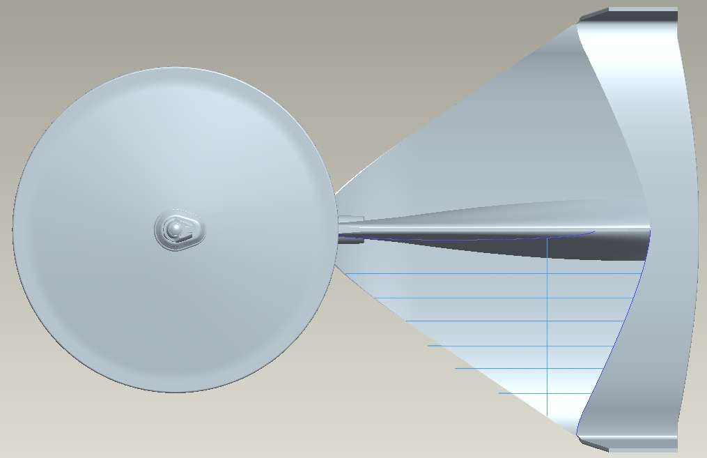
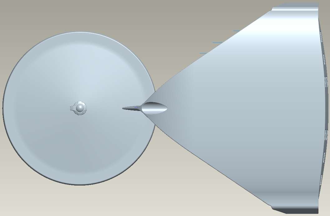
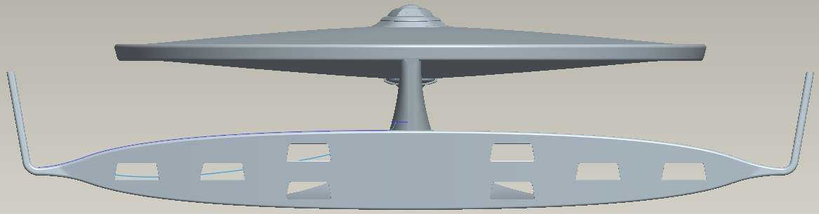
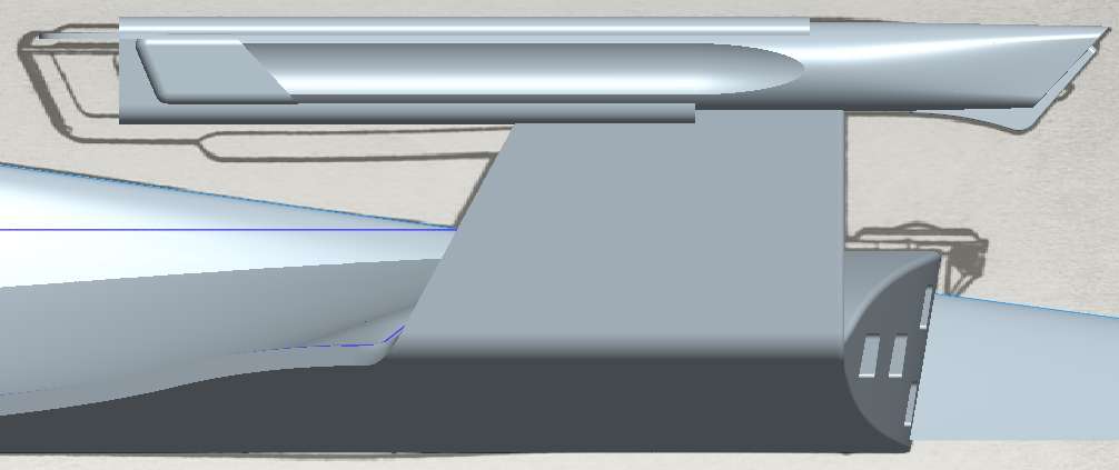
The top-down view is very close... but not totally exact. As I said before, I could add more sections to match the top-down view more closely, but I don't WANT to do that... I actually like the look I've got here better.

And that's all there is to it. Hope that helps... or at least is of some interest to the rest of you!
Another poster here, "Circusdog," has decided to start working on his own version of the classic 1701, and like me, he's using a CAD package (as opposed to a surface-modeler like Maya or Lightwave or the like).
He was having some trouble figuring out the best way to make the unusual shape of the B/C deck superstructure, and I've offered to post my step-by-step here to help him figure it out.
First... here's the topside of the Ariel's primary hull. I originally created it solely as a set of revolved shapes, and wasn't really planning to do this detail yet (since my focus remains on the secondary hull's complex topside). But I'll have to do it sooner or later, so I've gone ahead and done it now.
The first thing to do is to turn the revolved section into a smaller region, as seen below. It's important to make sure that you have the angle of the absent area as a changeable parameter, so you can simply adjust the angle of that cut-out area (and the tangent angle of the new section) on-the-fly as you tweak the shape.
Now, with the TOS Enterprise, the cylindrical "core" is perfectly adequate, but for TMP-era ships, you can't just sweep around a cylinder and get the shape right, so I added an additional volume to provide the "core" around which I'll be sweeping my shape. This should have a surface which is normal to the shape you want to achieve. I usually use conics to create this sort of shape... this path is defined by two symmetrical conic section, normal to the cut faces.
Now, you need to create the structure you'll be sweeping... a path, and at at least three sketches for cross-sections, as seen below. If you're not happy with the shape you're able to create using three sections, you can always add more (ensuring that they're symmetrical, obviously!). Each section needs to have the same number of drawing entities, and should have its origin at the same point, facing the same direction. I set my section origins in the innermost corner, facing upwards. If you don't get the origin right, the shapes will "twist" as the shape extrudes along the path, and you'll get a MESS.
(Note that you want the new, swept surfaces to be tangent to the existing surfaces. You need to have a surface adjacent to each of those sketch curve edges, so you can establish the tangency of the swept shape against those surfaces.)
I'll show the result of that sweep in no-hidden-line wireframe mode. Now, in this case, I wanted my upper "lip" and lower "lip" for the inset region to be unrelated, so I left the lower lip out of the first sweep. (This is not necessary for the TOS ship, obviously!)
I created a sweep profile for the lower lip... this is a 2D sketch I created, projected onto the surfaces of the inset region. I created three profiles, again, just as before.
Here's the result. Note that I've added a few rounds to help make it look more like a real object... the rounds were not part of the original sweeps.
At this point, you start comparing your shape to the sketches (which you should have been doing all along, obviously, but now you make it into the "final" shape). You tweak the various parameters in your shapes... the "cut-out angle" for example... and adjust things to get as close as you can to the drawn images.
The following two images allow you to compare my final result to the "trace sketch reference" I'm using. The lateral view is nearly perfect... and I'm not inclined to make any further tweaks here.
The top-down view is very close... but not totally exact. As I said before, I could add more sections to match the top-down view more closely, but I don't WANT to do that... I actually like the look I've got here better.
And that's all there is to it. Hope that helps... or at least is of some interest to the rest of you!